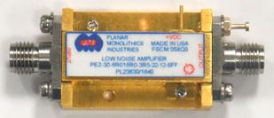
1.0 PMI Model No. PEAFS3-14-0R2535R0-6R5-23-12-292FF, 0.25 to 35.0 GHz, Low Noise Amplifier
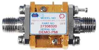
PMI Model No. PEAFS3-14-0R2535R0-6R5-23-12-292FF is a Low Noise Amplifier that operates over the 0.25 to 35.0 GHz frequency range. It has a typical gain of 14 dB and a typical noise figure of 6.5 dB. This model is outfitted with 2.92 mm female connectors in a housing measuring 0.53" x 0.70" x 0.26".
-
Frequency Range: 0.25 to 35.0 GHz
-
Gain: 14 dB Typ.
-
Gain Flatness: ±1.5 dB Max. - Measured ±1.39 dB
-
Noise Figure: 6.5 dB Typ. (Only Valid Above 2.0 GHz)
-
OP1dB: 23 dBm Min. - Measured 24.55 dB
-
VSWR Input/Output: 2.0:1 Max. - Measured 1.96:1
-
DC Supply: +12 to +15 VDC @ 300 mA Typ.
2.0 PMI Model No. EQL-DC40-6-292FF, DC to 40.0 GHz, Passive Equalizer
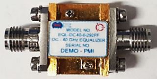
PMI Model No. EQL-DC40-6-292FF is a Passive Equalizer that operates over the DC to 40.0 GHz frequency range. It has a typical insertion loss of 2.5 dB and a maximum VSWR of 1.8:1. This model is outfitted with 2.92 mm female removable connectors in a housing measuring 0.53" x 0.70" x 0.26".
-
Frequency Range: DC to 40.0 GHz
-
Insertion Loss:
-
6.0 dB @ 10 MHz to 8.0 GHz Typ.
-
2.5 dB @ 38.0 to 40.0 GHz Typ.
-
VSWR: 1.6:1 Typ., 1.8:1 Max.
-
Slope: 0.15 ± 0.05 dB/GHz Typ. - Measured ±0.12 dB/GHz
-
Amplitude Accuracy: ±1 dB Typ. (Compared to Best Fit Straight Line) - Measured ±0.62 dB
-
Input Power: +30 dBm (1 W) Max.
3.0 PMI Model No. EQL-DC40-10-292FF, DC to 40.0 GHz, Passive Equalizer
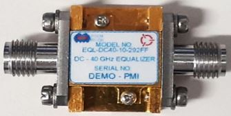
PMI Model No. EQL-DC40-10-292FF is a Passive Equalizer that operates over the DC to 40.0 GHz frequency range. It has a typical insertion loss of 2.0 dB and a maximum VSWR of 1.8:1. This model is outfitted with SMA female connectors in a housing measuring 0.53" x 0.70" x 0.26".
-
Frequency Range: DC to 40.0 GHz
-
Insertion Loss:
-
10.0 dB @ 10 MHz to 2.0 GHz Typ.
-
2.0 dB @ 38.0 to 40.0 GHz Typ.
-
Input Power: +30 dBm (1 W) Max.
-
VSWR: 1.6:1 Typ., 1.8:1 Max.
-
Slope: 0.25 ± 0.06 dB/GHz Typ.
-
Amplitude Accuracy: ±1 dB Typ. (Compared to Best Fit Straight Line)
4.0 PMI Model No. P8T-2G18G-60-T-SFF-NSI, 2.0 to 18.0 GHz, SP8T Absorptive Switch
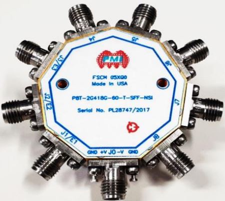
PMI Model No. P8T-2G18G-60-T-SFF-NSI is a 2.0 to 18.0 GHz Single Pole, Eight Throw, Absorptive Switch. It has a maximum insertion loss of 4.5 dB and a minimum isolation of 60 dB. It has SMA female connectors in a housing measured at ?1.50" x 0.40".
-
Frequency Range: 2.0 to 18.0 GHz
-
Insertion Loss:
-
2.5 dB Max. (2.0 to 6.0 GHz) - Measured 2.09 dB
-
3.5 dB Max. (6.0 to 12.0 GHz) - Measured 3.04 dB
-
4.5 dB Max. (12.0 to 18.0 GHz) - Measured 4.32 dB
-
Isolation: 60 dB Min. - Measured 64.7 dB
-
VSWR On In/Out: 2.0:1 Max. - Measured 1.9:1
-
VSWR Absorptive Out/Off: 2.0:1 Max.
-
Insertion Loss Flatness/1.0 GHz: ±0.5 dB Max.
-
RF Input Power: +20 dBm Max.
-
Switching Speed: 100 ns Max. - Measured 76.2 ns On, 33.2 ns Off, 55.6 ns Rise Time, 13.4 ns Fall Time
-
IIP3: 30 dBm Typ.
-
Impedance: 50 Ohms
-
Control: 3 Bit TTL Logic
-
Power Supply:
-
+5 V @ 300 mA Max. - Measured 125 mA
-
-5 V @ 100 mA Max. - Measured 55 mA
5.0 PMI Model No. P4T-1G18G-70-T-SFF, 1.0 to 18.0 GHz, SP4T Absorptive Switch
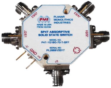
PMI Model No. P4T-1G18G-70-T-SFF is a Single Pole, Four Throw, Absorptive Switch that operates over the 1.0 to 18.0 GHz frequency range. It has a maximum insertion loss of 3.75 dB and a minimum isolation of 70 dB. This model is outfitted with SMA female connectors in a housing measuring 1.25" x 0.40".
-
Frequency Range: 1.0 to 18.0 GHz
-
Impedance: 50 Ohms
-
Input Power:
-
+30 dBm Max. (Survival)
-
+20 dBm Max. (Operating)
-
VSWR: 2.0:1 Max. - Measured 1.78:1
-
Insertion Loss: 3.75 dB Max.
-
Isolation: 70 dB Min. - Measured 73.65 dB
-
Insertion Loss Flatness (Variation from a Best Fit Straight Line): ±1 dB Max. - Measured ±0.74 dB
-
Amplitude Balance: ±0.5 dB Max. - Measured ±0.38 dB
-
Phase Balance: ±10° Max. - Measured ±9.5°
-
Switching Speed: 100 ns Max. - Measured 7.32 ns Rise Time, 13.45 ns Fall Time, 90.44 ns Speed On, 36.66 ns Speed Off
-
Hot Switching: 1 W (+30 dBm) Max.
-
P1dB: +32 dBm Min.
-
Video Transients: 3.3 V P-P Max. - Measured 3.15 V P-P Max., 648 mV P-P Min.
-
DC Voltage:
-
+5 VDC @ 200 mA Typ. - Measured 50 mA
-
-15 VDC @ 100 mA Typ.
6.0 PMI Model No. PS-360-DC-1 Option 911, 9.0 to 11.0 GHz, 8-Bit Digital Controlled Phase Shifter
PMI Model No. PS-360-DC-1 Option 911 is an 8-Bit Digital Controlled Phase Shifter that operates over the 9.0 to 11.0 GHz frequency range. It has a maximum insertion loss of 12.0 dB and a maximum VSWR of 2.0:1. This model is outfitted with SMA female connectors in a housing measuring 1.85" x 1.75" x 0.50".
-
Frequency Range: 9.0 to 11.0 GHz
-
Insertion Loss: 12.0 dB Max., 10.0 dB Typ.
-
VSWR: 2.0:1 Max.
-
Accuracy (Maximum): ±12° Max., ±9° Typ.
-
PM/AM (Maximum): ±2 dB Max.
-
Translation Rate: 0 to 500 kHz Min.
-
Carrier Suppression: Main Band: >20 dB Typ.
-
Side Band Suppression: Main Band: >20 dB Typ.
-
Phase Shift Range: 360° in 256 Steps
-
Control Input: 8-Bit TTL
-
Switching Speed 50% TTL to Within 10° of Final Phase Value: 500 ns Max.
-
Harmonics: >20 dBc Typ.
-
Power Handling Capability Without Performance Degradation: +13 dBm
-
Survival Power: +30 dBm
-
Power Supply:
-
+12 V ± 5% @ 250 mA - Measured 240 mA
-
-12 V ± 5% @ 20 mA - Measured 10 mA
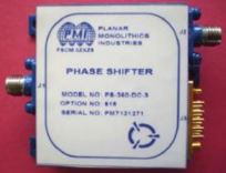
7.0 PMI Model No. PS-360-DC-3 Option 618, 6.0 to 18.0 GHz, 8-Bit Digital Controlled Phase Shifter
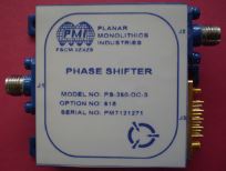
PMI Model No. PS-360-DC-3 Option 618 is an 8-Bit Digital Controlled Phase Shifter that operates over the 8.0 to 18.0 GHz frequency range. It has a maximum insertion loss of 12,0 dB and a maximum VSWR of 2.0:1. This model is outfitted with SMA female connectors in a housing measuring 1.85" x 1.75" x 0.50".
-
Main Band: 8.0 to 18.0 GHz
-
Stretch Band: 6.0 to 18.0 GHz
-
Insertion Loss: 12.0 dB Max., 10.0 dB Typ.
-
VSWR In/Out: 2.0:1 Max. - Measured 1.97:1/1.91:1
-
Accuracy (Maximum):
-
±12° (8.0 to 18.0 GHz) PK to PK
-
±15° (6.0 to 18.0 GHz) PK to PK
-
±1.7 dB (8.0 to 18.0 GHz)
-
±2.5 dB (6.0 to 18.0 GHz)
-
Translation Rate: 0 to 500 kHz
-
Carrier Suppresion:
-
Main Band: 25 dB
-
Stretch Band: 18 dB
-
Main Band: 20 dB
-
Stretch Band: 15 dB
-
Switching Speed: 50 ns Max.
-
Rise/Fall Time: 20 ns Max.
-
Phase Shift Range: 360° in 256 Steps
-
Control Input: 8-Bit TTL
-
Switching Speed 50% TTL to Within 10° of Final Phase Value: 500 ns Max.
-
Harmonics:
-
-30 dBc (8.0 to 18.0 GHz)
-
-25 dBc (6.0 to 8.0 GHz)
-
Power Handling Capability Without Performance Degradation: +10 dBm
-
Survival Power: +20 dBm
-
Power Supply:
-
+5 V ± 5% @ 115 mA - Measured 95 mA
-
-12 to -15 V @ 20 mA - Measured 16 mA
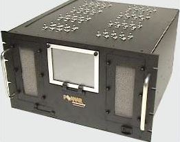
8.0 PMI Model No. RMR-818-77-NRL, 8.0 to 18.0 GHz, Microwave Pulse and CW Monitoring Receiver

PMI Model No. RMR-818-77-NRL is an 8.0 to 18.0 GHz, Microwave Pulse CW Monitoring Receiver. It has a maximum TSS of -77 dBm and a maximum input VSWR of 2.0:1. The housing is measured at 13.75" x 6.75" x 2.40".
-
Frequency Range: 8.0 to 18.0 GHz
-
Input VSWR: 2.0:1 Max.
-
TSS (Bandpass Filtered): -77 dBm Max.
-
Rise Time: 20 ns Typ., 30 ns Max.
-
Recovery Time: 200 ns Typ., 300 ns Max.
-
Dynamic Range: -75 to -10 dBm Min.
-
RF Power: 20 dBm Max.
-
AC Power: 115 ± 10 VAC
-
External Bandpass Filters:
-
Filter 1: 8.2 GHz Center 1.1 GHz Bandwidth
-
Filter 2: 9.2 GHz Center 1.1 GHz Bandwidth
-
Filter 3: 16.5 GHz Center 1.1 GHz Bandwidth
9.0 PMI Model No. RSM-618-65, 6.0 to 18.0 GHz, Receiver Front-End IFM Subsystem
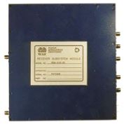
PMI Model No. RSM-618-65 is a 6.0 to 18.0 GHz, Receiver Front-End IFM Subsystem. It has a maximum TSS of -68 dBm and a maximum frequency flatness of ±2.5 dB. The housing is measured at 5.50" x 6.00" x 1.50" and has SMA female connectors.
-
Frequency Range: 6.0 to 18.0 GHz
-
Frequency Flatness: ±2.5 dB Max., ±1.75 dB Typ.
-
Dynamic Range: -65 to 0 dBm
-
Log Linearity: ±2.5 dB Max.
-
VSWR Input: 3.0:1 Max. @ -20 dBm, 2.5:1 Typ.
-
Tangential Sensitivity: -68 dBm Max.
-
Log Video Ouput Rise Time: 25 ns Max.
-
Log Video Output Slope: 50 mV/dB (±10% Max.)
-
Power Plus: +15 VDC @ <950 mA (850 mA Typ.)
-
Power Minus: -15 VDC @ <450 mA (275 mA Typ.)
-
RF Input Power: +15 dBm
-
Frequency Discriminator Video Ouputs (3 Outputs): 6.0 to 10.0 GHz, 10.0 to 14.0 GHz, 14.0 to 18.0 GHz
-
Frequency Discriminator Accuracy: ±300 MHz Max., ±200 MHz Typ.
-
Frequency Discriminator Slope: 50 mV/GHz (±10% Max.)
-
Pulse Width: 100 ns Min. (-65 to 0 dBm)
10.0 PMI Model No. RFE-218-70-BB Option JT, 2.0 to 18.0 GHz, Direction Finding Receiver Front End
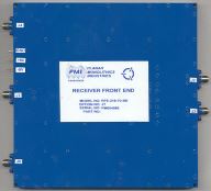
PMI Model No. RFE-218-70-BB Option JT is a 2.0 to 18.0 GHz, Direction Finding Receiver Front End. It has a minimum TSS of -63 dBm and a maximum VSWR of 3.0:1. The housing is measured at 6.00" x 6.00" x 0.50".
-
Frequency Range (J1, J2, J3): 2.0 to 18.0 GHz
-
Frequency Flatness (J4, J5): ±3.0 dB Max.
-
TSS (J4, J5): -63 dBm Min.
-
VSWR (J2, J3): 3.0:1 Max. - Measured 2.7:1
-
Dynamic Range (J4, J5): -60 to +5 dBm Min.
-
Log Linearity (J4, J5): ±2.25 dB Max. - Measured ±2.2 dB
-
Log Slope (J4, J5): 50 mV/dB (±10%)
-
Temperature Stability (J4, J5): ±2 dB Max. (-10°C to +85°C)
-
Rise Time (J4, J5): 30 ns Max. - Measured 23 ns
-
Recovery Time (J4, J5): 350 ns Max. - Measured 250 ns
-
Video Load (J4, J5): 93 Ohms (Recommended)
-
Isolation (J2 to J3): 24 dB Min.
-
Gain (J2 to J1 and J3 and J1): +3 dB Typ.
-
DC Power:
-
+9 to +12 V @ 850 mA Max. (With No RF Input) - Measured 750 mA
-
-9 to -12 V @ 300 mA Max. - Measured 250 mA
11.0 PMI Model No. P2T-1G18G-65-T-SFF, 1.0 to 18.0 GHz, SP2T Absorptive Switch
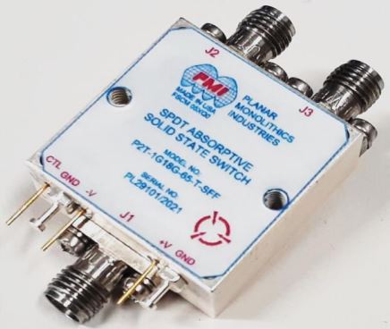
PMI Model No. P2T-1G18G-65-T-SFF is a 1.0 to 18.0 GHz, Single Pole, Two Throw, Absorptive Switch. It has a maximum insertion loss of 3.5 dB and a typical isolation of 65 dB. The housing is measured at 1.00" x 1.00" x 0.40" and has SMA female connectors.
-
Frequency Range: 1.0 to 18.0 GHz
-
Impedance: 50 Ohms
-
Input Power:
-
+30 dBm Max. (Survival)
-
+20 dBm Max. (Operating)
-
VSWR: 2.0:1 Max. - Measured 1.82:1
-
Insertion Loss: 3.5 dB Max. - Measured 3.17 dB
-
Isolation: 65 dB Typ. - Measured 78.32 dB
-
Switching Speed: 100 ns Max. - Measured 10.45 ns Rise Time, 7.09 ns Fall Time, 36.63 ns Speed On, 32.36 ns Speed Off
-
Hot Switching: 1 W (+30 dBm) Max.
-
Phase Balance: ±10° Max. - Measured ±7.64°
-
Amplitude Balance: ±0.5 dB Max. - Measured ±0.32 dB
-
P1dB: +33 dBm Min. - Measured +35 dBm @ 18.0 GHz
-
IIP3: +40 dBm MIn. - Measured +43.39 dBm
-
OIP3: +40 dBm Typ. - Measured +42.085 dBm
-
Video Transiets: 3.3 V P-P Max. - Measured 2.78 V P-P Max., 1.02 V P-P Min.
-
DC Voltage:
-
+5 VDC @ 100 mA Typ. - Measured 63 mA
-
-15 VDC @ 100 mA Typ. - Measured 78 mA
https://www.pmi-rf.com/product-details/p2t-1g18g-65-t-sff-
12.0 PMI Model No. LNA-20-17-5-SFF, 1.0 to 7.0 GHz, Low Noise Amplifier
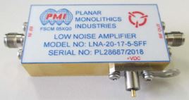
PMI Model No. LNA-20-17-5-SFF is a 1.0 to 7.0 GHz, Low Noise Amplifier. It has a minimum gain of 20 dB and a noise figure of 5 dB. The gold plated housing is measured at 2.00" x 1.00" x 0.50" and has SMA mm female connectors.
-
Frequency Range: 1.0 to 7.0 GHz
-
Ouput Power P1dB: 22 dB - Measured 23.6 dBm
-
Gain: 20 dB Min., 26 dB Max.
-
Gain Flatness: ±2.0 dB - Measured ±0.6 dB
-
Noise Figure: 5 dB - Measured 3.5 dB
-
VSWR In/Out: 2:1 - Measured 1.8:1/1.9:1
-
Minimum Third Order Intercept Point: 32 dBm - Measured 34 dBm
-
Typical Saturated Output Power: 24 dBm - Measured 25.6 dBm
-
Harmonics: -12 dBc
-
Non-Harmonic Spurious: -50 dBc
-
Stability: Unconditional
-
Cooling: Convection
-
DC Voltage: 15 V
-
DC Current: 900 mA - Measured 480 mA
13.0 PMI Model No. LNA-46-17-5-SFF, 1.0 to 7.0 GHz, Low Noise Amplifier

PMI Model No. LNA-46-17-5-SFF is a 1.0 to 7.0 GHz, Low Noise Amplifier. It has a minimum gain of 46 dB and a noise figure of 5 dB. The unit is supplied in a gold plated housing measuring 2.70" x 1.00" x 0.50" and has SMA female connectors.
-
Frequency Range: 1.0 to 7.0 GHz
-
Output Power P1dB: 23 dBm
-
Gain: 46 dB Min., 54 dB Max.
-
Gain Flatness: ±2 dB - Measured ±1.1 dB
-
Noise Figure: 5 dB - Measured 1.9 dB
-
VSWR In/Out: 2:1 - Measured 1.9:1
-
Minimum Third Order Intercept Point: 30 dBm - Measured 33.1 dBm
-
Typical Saturated Output Power: 25 dBm - Measured 26.8 dBm
-
Harmonics: 12 dBc
-
Non-Harmonics Spurious: 50 dBc
-
Stability: Unconditional
-
Cooling: Convection
-
DC Voltage: 15 V
-
DC Current: 1100 mA - Measured 650 mA
14.0 PMI Model No. LNA-47-0R52-4-SFF, 0.5 to 2.0 GHz, Low Noise Amplifier
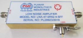
PMI Model No. LNA-47-0R52-4-SFF is a 0.5 to 2.0 GHz, Low Noise Amplifier. It has a minimum gain of 47 dB and a noise figure of 4 dB. The gold plated housing is measured at 2.50" x 1.00" x 0.50" and has SMA female connectors.
-
Frequency Range: 0.5 to 2.0 GHz
-
Output Power P1dB: 20 dBm - Measured 22.1 dBm
-
Gain: 47 dB Min., 53 dB Max.
-
Gain Flatness: ±1.25 dB - Measured ±0.5 dB
-
Noise Figure: 4 dB - Measured 1.6 dB
-
VSWR In/Out: 2:1 - Measured 1.8:1/1.7:1
-
Minimum Third Order Intercept Point: 30 dBm - Measured 33.2 dBm
-
Typical Saturated Output Power: 23 dBm - Measured 25.3 dBm
-
Harmonics: -12 dBc
-
Non-Harmonic Spurious: -50 dBc
-
Stability: Unconditional
-
Cooling: Convection
-
DC Voltage: 15 V
-
DC Current: 600 mA
15.0 PMI Model No. HP2G-1780-CD-SS-ROHS, 2.0 to 18.0 GHz, Suspended High Pass Filter
PMI Model No. HP2G-1780-CD-SS-ROHS is a 2.0 to 18.0 GHz, Suspended High Pass Filter. It has a typical VSWR in the passband of 1.5:1 and a typical insertion loss in the passband of 0.5 dB. The housing is measured at 0.75" x 0.75" x 0.50" and has SMA female connectors.
-
Passband: 2.0 to 18.0 GHz
-
3 dB Bandwidth: 1.78 GHz
-
VSWR in the Passband: 1.5:1 Typ.
-
Insertion Loss in the Passband: 0.5 dB Typ.
-
Rejection @ 0.87 GHz: 80 dB Min.
16.0 PMI Model No. PDPS-3F-6 Option AL, 3.0 GHz, 6-Bit Phase Shifter
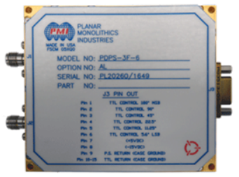
PMI Model No. PDPS-3F-6 Option AL is a 3.0 GHz, 6-Bit Phase Shifter. It has a maximum insertion loss of 10 dB and a VSWR of 2.0:1. The housing is measured at 3.00" x 2.70" x 0.53" and has SMA female connectors.
-
Frequency Range: 3.0 GHz (Bandwidth 500 MHz)
-
Insertion Loss: 9 dB Typ., 10 dB Max. - Measured 4 dB
-
VSWR In/Out: 2.0:1 - Measured 1.4:1/1.5:1
-
Phase States: 5.6°, 11.2°, 22.4°, 45°, 90°, 180°
-
Phase Accuracy (@ 5.6°): ±6° Max., 3° Typ. @ 3.0 GHz - Measured 1.8°
-
Phase Accuracy (@ 11.2°): ±6° Max., 3° Typ. @ 3.0 GHz - Measured -0.6°
-
Phase Accuracy (@ 22.5°): ±6° Max., 3° Typ. @ 3.0 GHz - Measured 1.2°
-
Phase Accuracy (@ 45°): ±6° Max., 3° Typ. @ 3.0 GHz - Measured 1.8°
-
Phase Accuracy (@ 90°): ±6° Max., 3° Typ. @ 3.0 GHz - Measured -1.7°
-
Phase Accuracy (@ 180°): ±6° Max., 3° Typ. @ 3.0 GHz - Measured 2.4°
-
Switching Speed: 300 ns Max., 100 ns Typ. - Measured 70 ns
-
Power Supply:
-
+5 V @ 70 mA Typ., 100 mA Max. - Measured 1 mA
-
-15 V @ 70 mA Typ., 100 mA Max. - Measured 11 mA
17.0 PMI Model No. 5399723+001 Rev. L, 29.8 to 30.2 MHz, 7-Bit Attenuator
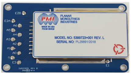
PMI Model No. 5399723+001 Rev. L is a 29.8 to 30.2 MHz, 7-Bit Attenuator. It has a maximum insertion loss of 9 dB and a maximum input power of +10 dBm. The hermetically sealed housing is measured at 3.675" x 2.250" x 0.230".
-
Frequency Range: 29.8 to 30.2 MHz
-
Input/Output Impedance: 50 Ohms
-
Input/Output VSWR: 1.4:1 Max. - Measured 1.33:1/1.32:1
-
Input Power: +10 dBm Max.
-
Insertion Loss: 9 dB Max. - Measured 8.6 dB
-
Attenuation Range: 0 to 63.5 dB, In 0.5 dB Steps
-
Attenuation Accuracy (Normalized to Insertion Loss):
-
0 to 4 dB: ±0.2 dB - Measured ±0.15 dB
-
5 to 9 dB: ±0.3 dB - Measured ±0.14 dB
-
10 to 16 dB: ±0.5 dB - Measured ±0.21 dB
-
17 to 24 dB: ±0.6 dB - Measured ±0.13 dB
-
25 to 30 dB: ±0.7 dB - Measured ±0.25 dB
-
31 to 40 dB: ±0.7 dB - Measured ±0.25 dB
-
41 to 50 dB: ±0.7 dB - Measured ±0.25 dB
-
51-63.5 dB: ±2% of Attenuation Value - Measured ±0.69%
-
Attenuation vs. Frequency: 0.1 dB Peak to Peak - Measured 0.09 dB
-
Linearity (Over Any 6 dB Range): 0.5 dB Peak to Peak up to 50 dB Attenuation - Measured 0.14 dB
-
Insertion Phase: 30° ± 5°
-
Phase vs. Frequency: 2.8° Peak to Peak - Measured 2.51°
-
Phase vs. Attenuation: 3.0° Peak to Peak, 0 to 44.0 dB: 7.5° Peak to Peak, 44.5 to 50.0 dB
-
Control Input Impedance: 8 Equivalent TTL Loads Max., Including 1k Pull-Up Resistors
-
Control Input Logic: TTL Driver with Rise/Fall of 20 ns
-
Binary Code: 7 Bits, 0000000 = Insertion Loss
-
Attenuation Per Bit: A0 = LSB = 0.5 dB, A6 = MSB = 32 dB
-
Switching Speed (Control Signal 3 us Pulse, 50% Duty Cycle, 10 KHz PRF): 650 ns Delay Max., 500 ns Rise Time Max. - Measured 68 ns Delay, 128 ns Rise
-
Switching Rate: 10 kHz Max.
-
Power Supply: +5.0 to +5.2 VDC @ 750 mA Max. - Measured 236 mA
-
Transients:
-
5 mV Peak to Peak for 0.5 dB Steps - Measured 1.9 mV Peak to Peak
-
10 mV Peak to Peak for 63.5 dB Step - Measured 4.8 mV Peak to Peak
18.0 PMI Model No. 5399723+002 Rev. L, 29.8 to 30.2 MHz, 7-Bit Attenuator
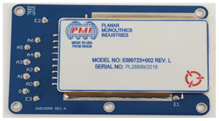
PMI Model No. 5399723+002 Rev. L is a 29.8 to 30.2 MHz, 7-Bit Attenuator. It has a maximum insertion loss of 9 dB and a maximum input power of +10 dBm. The hermetically sealed housing is measured at 3.675" x 2.250" x 0.230".
-
Frequency Range: 29.8 to 30.2 MHz
-
Input/Output Impedance: 50 Ohms
-
Input/Output VSWR: 1.4:1 Max. - Measured 1.35:1/1.34:1
-
Input Power: +10 dBm Max.
-
Insertion Loss: 9 dB Max. - Measured 8.7 dB
-
Attenuation Range: 0 to 63.5 dB, In 0.5 dB Steps
-
Attenuation Accuracy (Normalized to Insertion Loss):
-
0 to 4 dB: ±0.2 dB - Measured ±0.11 dB
-
5 to 9 dB: ±0.3 dB - Measured ±0.1 dB
-
10 to 16 dB: ±0.5 dB - Measured ±0.14 dB
-
17 to 24 dB: ±0.6 dB - Measured ±0.17 dB
-
25 to 30 dB: ±0.7 dB - Measured ±0.22 dB
-
31 to 40 dB: ±0.7 dB - Measured ±0.22 dB
-
41 to 50 dB: ±0.7 dB - Measured ±0.22 dB
-
51-63.5 dB: ±2% of Attenuation Value - Measured ±0.34%
-
Attenuation vs. Frequency: 0.1 dB Peak to Peak - Measured 0.09 dB
-
Linearity (Over Any 6 dB Range): 0.5 dB Peak to Peak up to 50 dB Attenuation - Measured 0.16 dB
-
Insertion Phase: 30° ± 5°
-
Phase vs. Frequency: 1.4° Peak to Peak
-
Phase vs. Attenuation: ±1.5° 0 to 40 dB, Referenced to Insertion Phase - Measured ±1.25°
-
Control Input Impedance: 8 Equivalent TTL Loads Max., Including 1k Pull-Up Resistors
-
Control Input Logic: TTL Driver with Rise/Fall of 20 ns
-
Binary Code: 7 Bits, 0000000 = Insertion Loss
-
Attenuation Per Bit: A0 = LSB = 0.5 dB, A6 = MSB = 32 dB
-
Switching Speed (Control Signal 3 us Pulse, 50% Duty Cycle, 10 KHz PRF): 700 ns Delay Max., 700 ns Rise Time Max. - Measured 68 ns Delay, 128 ns Rise
-
Switching Rate: 10 kHz Max.
-
Power Supply: +5.0 to +5.2 VDC @ 750 mA Max. - Measured 242 mA
-
Transients:
-
5 mV Peak to Peak for 0.5 dB Steps - Measured 1.9 mV Peak to Peak
-
10 mV Peak to Peak for 63.5 dB Step - Measured 4.8 mV Peak to Peak
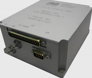
19.0 PMI Model No. PTB-35-120-5R0-10-115-VAC-SFF, 1.0 to 20.0 GHz, Portable Amplifier
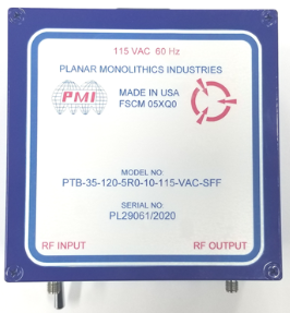
PMI Model No. PTB-35-120-5R0-10-115-VAC-SFF is a 1.0 to 20.0 GHz, Portable Amplifier. It has a typical gain of +35 dB and a maximum noise figure of 5.0 dB. The housing is measured at 4.92" x 4.92" x 2.26" and has SMA female connectors.
-
Frequency Range: 1.0 to 20.0 GHz
-
Gain: +35 dB Typ. - Measured +41.9 dB
-
Gain Flatness: ±3.0 dB Typ. - Measured ±1.05
-
Noise Figure: 5.0 dB Max. - Measured 4.1 dB
-
OP1dB: +10 dBm Min. - Measured +11.5 dBm
-
VSWR In/Out: 2.0:1 Max. - Measured 1.5:1/1.8:1
-
AC Voltage Supply: 115 VAC, 60 Hz
20.0 PMI Model No. DD-20-218-5PF-1-N-M, 2.0 to 18.0 GHz, Diode Detector
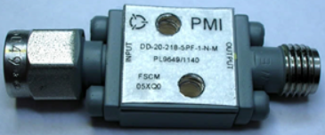
PMI Model No. DD-20-218-5PF-1-N-M is a 2.0 to 18.0 GHz, Diode Detector. It has a typical VSWR of 3.5:1 and a maximum input power of +17 dBm. The housing is measured at 0.50" x 0.50" x 0.22" and has a SMA female and a SMA male connector.
-
Frequency Range: 2.0 to 18.0 GHz
-
VSWR In/Out: 3.5:1 Typ. (Measured @ -23 dBm with 27 K Ohm Load Impedance) - Measured 2.94:1
-
Frequency Flatness: ±1.5 dB, ±1.0 dB Typ.
-
Speed: 5 ns
-
Voltage Sensitivity: 650 mV/mW, 700 mV/mW Typ.
-
Tangential Sensitivity: -50 dBm @ 2 MHz Video Bandwidth (With 2 dB Noise Figure Amplifier)
-
Video Capacitance: 5.6 pF
-
Output Voltage: Negative is Standard (Positive is Available)
-
Max Input Power: +17 dBm
21.0 PMI Model No. MSDLVA-2020-70 Options 48, SE, 4.0 to 18.0 GHz, SDLVA
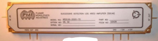
PMI Model No. MSDLVA-2020-70 Options 48, SE is a 4.0 to 18.0 GHz, SDLVA. It has a typical TSS of -73 dBm and a pulse width range of 50 ns to CW. The housing is measured at 4.60" x 0.98" x 0.24".
-
Frequency Range: 4.0 to 8.0 GHz (Other Frequencies Available)
-
Logging Range: -65 to +15 dBm
-
Log Linearity: ±2.0 dB Max., ±1.6 dB Typ.
-
Frequency Flatness: ±1.0 dB Typ., ±2.0 dB Max.
-
Pulse Width Range: 50 ns to CW
-
RF Out SAT: +14 dBm ± 1.0 dB Max. (-60 to +10 dBm)
-
TSS: -73 dBm Typ., -70 dBm Max.
-
Input VSWR: 1.6:1 Typ., 2.0:1 Max.
-
Log Video Ouput:
-
Rise Time: 25 ns Max.
-
Settling Time: 40 ns Max.
-
Recovery Time: 150 ns Typ.
-
Log Slope: 50 mV/dB (Not Critical)
-
Video Load: 100 Ohms
-
+12 VDC @ 570 mA Typ., 600 mA Max.
-
-12 VDC @ 150 mA Typ., 180 mA Max.
|
|